Support for continuous stalling when homing.
If you need a replacement: Y-Axis limit switches are sold here
Homing fail (Y axis)
This refers to the homing movement of the beam towards the home end of the bench, not stopping at the desired home position, and entering a continuous stall.
Intent
When homing, the first operation drives the beam towards the home end of the bench.
A reed switch sits on the lower beam, and a magnet sits in the home end plate of the bench.
Therefore, when the reed switch arrives at the magnet, the magnet triggers the reed switch and the beam automatically stops moving, before completing the rest of its homing checks.
Issue description
In the rare event that the reed switch is not triggered, the beam will not know that it has reached the home position and will continue to drive the beam into the legs, causing a loud stalling noise until the machine is manually stopped, or the machine times-out after several tens-of seconds. This symptom is referred to as a failed home switch.
General causation
The machine will not have left the factory with this fault, because it would have not been able to complete final test without the homing switch operating correctly. But if a problem is witnessed in the field, there are a few possible causes for the failure - likely due to damage of some kind (either shipping or accidental misuse), either to the magnet or the switch.
|

|
If you home SmartBench with auto-squaring, SmartBench will make a brief stalling noise. This is normal and should only last for 2 seconds.
This normal operation should not be confused with a failed homing switch, which will cause SmartBench to continuously stall for much longer than 2 seconds.
|
Immediate checks
Remove the bench panel nearest the home end - this will make inspection simpler.
Mechanical blockage
Are there any components that are preventing the beam from getting to the home end of the bench? Is the beam genuinely stalling against a blockage?
With the power off, manually push the beam towards the home end of the bench.
Make sure that the beam can reach the end of the bench: the plates of the lower beam should be able to touch the legs of the bench completely.
Look out for:

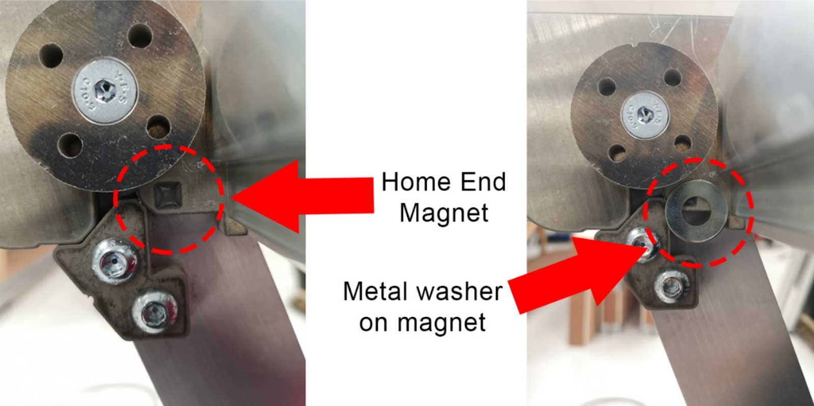
Magnet damage
Is the home end magnet present?
Visually check that a magnet is present.
Is the magnet intact?
A damaged magnet (look for cracks or debris) may not be able to generate enough of a magnetic field to trigger the reed switch. Offer up a piece of ferrous metal to the magnet (it should hold the weight of a metal washer.)
Reed switch
Slide the beam away from the home end to a position where the reed switch can be easily inspected.
Remove a bench panel to view inside.
Does the reed switch respond at all?
Offer a magnet up to the home reed switch. With a magnet next to the home reed switch, this should trigger an alarm screen on the Console.

If an alarm screen is not triggered with the magnet next to the home switch
The reed switch is permanently damaged. Most likely this is due to direct hit, or excessive vibration in transit. Contact your reseller with the diagnosis.
If an alarm screen is triggered with the magnet next to the home switch
The switch may be operating correctly or intermittently.
If the switch is only operational intermittently:
-
It has been reported that the switch can be “woken up” with a strong magnetic field (magnet), and operations can be resumed. This can be likened to a “sticky” switch.
-
The magnetic field from the Home magnet may have been weakened to a point where it is insufficient. It has been reported that a workaround can be affected by leaving a second magnet over the first, allowing the machine to home.
Advanced Diagnosis
Does the reed switch respond at all?
In the PRO app, go to the settings tab and look at the status monitor.
Any values after the Pn: section represent which switches are getting triggered (if the symbol does not appear, it means the switch is not triggered).

Offer a magnet up to the home reed switch.
This should trigger an alarm screen: in later software versions you can see SmartBench’s status in the alarm report: with a magnet next to the home reed switch, the status should include a “y” symbol after the Pn:.
In earlier versions, you may have to press “Return” to get back to the GCode monitor, and then press “Reset” in the sidebar to see the status update. With a magnet next to the home reed switch, the status should include a “y” symbol after the Pn:.
|
|
Note that other symbols may appear after the Pn: - this is normal depending on the status of other switches on the machine (see the appendix for the definition for the various symbols).
|
If there is no alarm screen
There may be an issue with the GRBL settings. Head to the CAD/CAM application on your console - Click on the settings cog on the right hand side to access the Gcode monitor (More information here on how to access the gcode monitor) - press the “Settings” button next to the GCode monitor, and in the output check that $21=1.
If it does not, enter “$21=1” into the textbox at the top of the GCode monitor, and press enter, close the warning and then press enter again. Then repeat the magnet test to see if the reed switch responds.
Replacing a switch
If you have been sent replacement Y limit switches, they can easily be replaced on your lower beam.
Remove the 2 hex bolts on the top side of the Y limit switch bracket, and the single PZ1 screw on the underside using the correct tools.


You can then remove the bracket, the switches are attached to the loom with a black connector.
Replace the switches and re-fit ensuring the wires are connected to the correct switch. as on the image below
Blue - Home End
Black - Max End

Appendix
Any values after the Pn: section of the status monitor represent which switches are getting triggered:
|
Pn: Symbol (note there is a difference between upper and lower cases)
|
Switch
|
|
x
|
X axis home
|
|
X
|
X axis max
|
|
y
|
Y axis home
|
|
Y
|
Y axis max
|
|
Z
|
Z axis home
|
|
p
|
Probe plate (stored)
|
|
G
|
Dust shoe guard (open)
|