This article is the second step of the CNC Stylus drawing tutorial. We draw features which will later be used to define toolpaths.
< Previous | List | Next >
Draw text
First, we will create the text using the same font and size as the sign.
Click on Draw Text

Define the parameters for the text:

Confirm by clicking on the Close button. The text will appear on the job screen.

Click on the text, the colour of outlines will change to magenta. Go to Edit > Align Selected Objects > Center In Material

We are now going to add secondary text just like in the previous steps.
Define the parameters for the text:

Confirm by clicking on the Close button. The text will appear on the job screen.

We can now align this just as we did before.

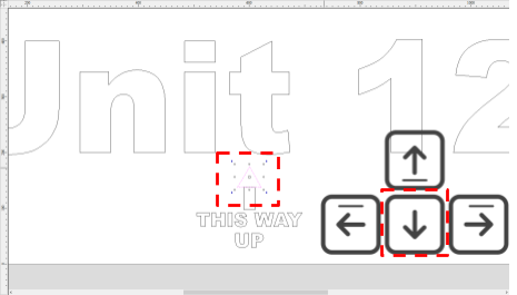
To move an object, click on it twice until the object is highlighted in magenta with the anchor points showing. You can use the arrow keys on your keyboard to move the object.

Draw arrow
We are now going to draw the arrow.
Click on Draw Rectangle

Define the parameters of the rectangle
-
Width (X): 20mm
-
Length (Y): 40mm
-
Corner type: Square

Confirm by clicking on the Create button. The rectangle will appear on the job screen.

Click on the rectangle, the colour of outlines will change to magenta. Go to Edit > Align Selected Objects > Center Horizontally in Material

To move an object, click on it twice until the object is highlighted in magenta with the anchor points showing. You can use the arrow keys on your keyboard to move the object.

We are now going to draw the arrow.
Click on Draw Polygon

Define the parameters of the triangle

Confirm by clicking on the Create button. The triangle will appear on the job screen.

Click on the triangle, the colour of outlines will change to magenta. Go to Edit > Align Selected Objects > Center Horizontally in Material

To move an object, click on it twice until the object is highlighted in magenta with the anchor points showing. You can use the arrow keys on your keyboard to move the object.
To trim and join vectors (rectangle and triangle), select the Interactive Trim tool

Trim the vectors to join the 2 objects


Draw mounting holes
Next we will draw some circles to act as the mounting holes:
Click on Draw Circle

Define the parameters for the circle:

Confirm by clicking on the Create button. The circle will appear on the job screen:

We can now click the circle twice which will highlight it in magenta and show the anchor points. Now, move the circle into place using our mouse to click and drag.

We need to create 17 circles in total. To create a copy, we can select the object and press CTRL + C, and then CTRL + V to paste

Once you have created all of your circles and moved them to the correct location it should look like this

< Previous | List | Next >