This article will show the procedure on how to reassemble the Z Head.
< Previous | List |
|

|
The reassembly instructions in this section are for Z Head 2b only. To identify which Z Head version you are using click here.
|
Now that you have fitted the replacement X limit switches, it's time to reassemble the Z Head.
Ensure that you have all of the original components.
A: Z Head case
B: Z Head top plate
C: Belt
D: Spacers
E: Probe plate
F: Dust shield for the probe plate connection socket
G: Dust shield for the probe plate housing
H: Signal cable shield
I: Extraction elbow

Just in case you forget which bolt will fasten which component, here is a list of screws used in assembling Z Head.
J: M5x35 dome socket head (4 screws for the top plate)
K: M4X10 dome socket head (2 screws for removing the casing)
L: M4X10 socket head black (2 screws for removing the extraction elbow)
M: M3X6 dome socket head (8 screws for removing shield casing)
N: M3X10 socket head with washer (4 screws with washer for removing the motor)

Reassemble the casing on the back of the Z Head
The main case needs to be put back onto the Z Head first.
Orient the case so that the long slot in the case will line up with the probe plate housing in the Z Head.
Push the case onto the Z Head, as shown in the image. The slots in the case should slide easily around the component housings.

Attach the extraction elbow onto the Z Head base plate with two screws (M4X10 socket head black). Use a 2mm allen key to tighten the screws.

Reassemble the components on the left hand side of the Z Head
On the left hand side of the Z Head, attach the signal cable shield, and secure it with two screws (M3X6 dome socket head). Use a 2mm allen key to tighten the screws.

Reassemble the components on the right hand side of the Z Head
Use a 2mm allen key to attach the dust shield onto the probe plate connection socket with two screws (M3X6 dome socket head).

Use a 2mm allen key to attach the dust shield onto the probe plate housing with two screws (M3X6 dome socket head).

Insert the probe plate into its housing, and then plug in the probe plate connector.

Reassemble the components on the top of the Z Head
Use a 2mm allen key to fasten the two screws (M4X10 dome socket head) which secure the top of the casing.
Mount the motor back into the top plate of the Z Head.
The motor housing needs to sit under the top plate, and the shaft of the motor (which the belt will go round) goes through the hole in the top plate.
Use a 2.5mm allen key to loosely secure the motor with the four mounting screws (M3X10 socket head with washer).
|

|
The screws should be tight enough to hold the motor against the top plate, and loose enough that it can be easily moved back and forth in its mount.
This flexibility is needed to adjust the belt in the next stage.
|


Push the motor as close to the casing as possible, and loop the belt around the motor and the bearings.

Loop the belt around the bearings as shown in the image below:

Once the belt is set, pull the motor away from the casing to increase tension on the belt.
|
|
Make sure the belt is tight enough and not loose. A loose belt will not be gripped properly.
|

Once the tension is set on the belt, use a 2.5mm allen key to tighten the four motor screws (M3X10 socket head with washer).
The motor screws should be tight enough that the motor is completely fixed in place.
O: Belt
P: Motor

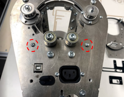
Place all four spacers highlighted in the image on their hole positions.

Place the top plate off the Z Head with all four screws (M5x35 dome socket head) going into their respective spacers.

Use a 3mm allen key to secure the top plate.

A fully assembled Z Head looks like this:
Q: Z Head top plate

Mount the Z Head back onto the Upper X Beam (click here to learn how).
Load the spindle back into the Z Head (click here to learn how).

<Previous | List |