This article will show you how to re-fit the X limit switches.
< Previous | List | Next >
We will show you how to re-fit both X axis switches.
|

|
You may only need to replace one switch. Click here for help diagnosing failed X axis limit switches.
|
Go to the following sections for:
Re-fitting X axis home switch
The X axis home switch has closed slots, as shown in the image below.

Attach a new X axis limit switch to its corresponding tab, as shown in the image.
|

|
The tab is used to release strain on the wire.
|
X axis home limit switch slots into the tab as shown in the image.
A: Tab
B: X axis home limit switch

A: M4 x 8 (socket head stainless)
B: Limit switch tab
C: X axis limit switch (home)

The tab and limit switch will be fixed to the lower plate of the Z Head, on the side that normally sits closest to SmartBench’s home position.
Use a 2mm allen key to screw both screws (M4 x 8 socket head stainless) through the tab, and into the Z plate.

Connect the X axis home limit switch to the connector with the blue sleeve.
D: Blue sleeve connector from Z Head
E: X axis home switch
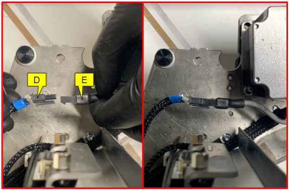
Your new X axis home limit switch is now installed.
F: X axis home limit switch

Click here to jump straight to reassembling the Z Head casing.
Re-fitting X axis max switch
The X axis max switch has open slots, as shown in the image below.

The tab and limit switch will be fixed to the lower plate of the Z Head, on the side that normally sits closest to SmartBench’s X max position.
Use a 2mm allen key to screw both screws (M4 x 8 socket head stainless) through the slots of the limit switch, and into the Z plate.
A: M4 x 8 (socket head stainless)
C: X axis limit switch

Connect the X axis max limit switch to the connector with the black sleeve.
G: Black sleeve connector from Z Head
H: X axis max switch

Check that the connector sits vertically along the side of the Z Head, as shown below.
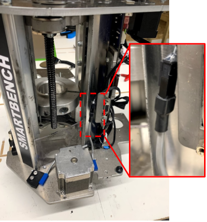
Your new X axis max limit switch is now installed.
I: X axis max limit switch

Click here to jump straight to reassembling the Z Head casing.
<Previous | List | Next >