This article will explain how to diagnose and replace your failed X axis limit switches.
| List | Next >
If you need a replacement: X-Axis limit switches are sold here
Where are the X axis limit switches?
There are two X axis limit switches to detect each limit of the X axis (X-home and X-max), and both are located on the Z Head.
They sit either side of the motor, on the side of the Z Head that is closest to Y-home.
A: X axis home
B: X axis max

How are the X axis limit switches triggered?
The limit switches are triggered when they come in contact with a magnetic field.
|

|
Ensure the operator and the workpiece has no magnetic elements which could cause a false trigger for the limit switches, as this will cause SmartBench to halt.
|
Here, we will show you two situations when the X axis limit switches will normally trigger:
While homing SmartBench
When homing, the Z Head moves towards the home end of the X beam. The X axis home limit switch is on the Z Head, and there is a magnet (C) on either end of the X Beam.
SmartBench detects that the Z Head has reached the end of the X Beam when the X axis home limit switch is triggered, and sets its home position accordingly.
|

|
SmartBench is using the limit detection to set its home position, so it will not display alarm screens when the limit switches are triggered.
|
The X axis home switch is moved away from the magnet after the homing cycle has been completed.
|
|
If the X axis home switch is faulty, or the magnet is damaged, SmartBench will not be able to complete the homing sequence.
|
C: Magnet on home end plate
D: X axis home limit switch
E: X axis max limit switch


When there is a shift in the X axis
Pushing or pulling the Z Head out of place will cause SmartBench to lose position, and as a result, SmartBench will not know where the limits of the X axis are.
When the Z Head has been pulled or push after homing, this can cause problem in machining for instance:
-
You will see a shift in the X axis, meaning your workpiece will not get machined with respect to your datum position and you will see stalling, skipped cuts or the cut stretching out of the workpiece.
If SmartBench is then moved towards either end of the X axis, the magnets on the X Beam will eventually trigger one of the limit switches, and cause an alarm.

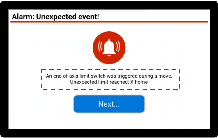
Understanding an alarm on the Console
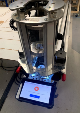
When a limit switch is triggered, the SmartBench Console will show you an alarm screen with details of the triggered switch.
Click here to learn more about alarm states.
Diagnosing the failed switch
If a limit switch is working normally, it should cause an alarm when it is close to a magnet: the Z Head LEDs will turn white, and an alarm screen will come up on the Console.
A failed limit switch can be over-sensitive or under-sensitive (or a mixture of both).
Under-sensitive limit switches
An under-sensitive limit switch will not respond to a magnetic trigger or cause an alarm, and SmartBench may try to keep moving beyond its limits while homing.
There are two ways to tell if a limit switch is not always sensitive enough.
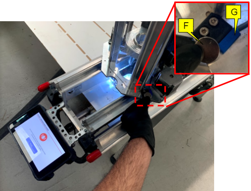
Test switches using a magnet
You can test the switches by using a magnet to check whether they trigger or not.
Hold the test magnet against each switch in turn, and observe if SmartBench goes into an alarm state.
Make sure you clear any alarm states between tests.
|
|
If SmartBench is already in an alarm state, it will not go into a new one if a different limit is triggered.
|
F: Magnet (for testing)
G: X axis home limit switch
H: X axis max limit switch

If an alarm screen is not triggered with the magnet next to the switch
This indicates the limit switch is permanently damaged and needs to be replaced.
If an alarm screen is triggered only with a test magnet next to the switch
This means that the magnetic field of the corresponding limit magnet (at X-home or X-max) has weakened and needs to be replaced.
You can confirm this by seeing whether the limit magnet can hold a bolt, if not then this would need to be replaced.

Observable symptom: stalling during homing
If the X axis home limit switch is not as responsive, it can cause excessive stalling during homing.
|
|
The X axis max limit switch is not used during homing, so needs to be tested for unresponsiveness using a magnet.
|
In the following example, the X axis home switch (A) is faulty.
Firstly, home SmartBench. Click here to learn more about homing.
I: X axis home

The Z Head will move towards the home end of the Upper X Beam
J: Z Head
K: X Beam home end.

Normally, the limit switch would be triggered by the magnetic field at the home end of the X Beam.
If the limit switch is faulty, it will not detect the magnetic field and so the Z Head will continuously run into the home end of the X Beam.
|
|
This will make a loud stalling noise, and you will need to tell SmartBench to stop.
|

The limit may or may not eventually trigger and cause an alarm screen.

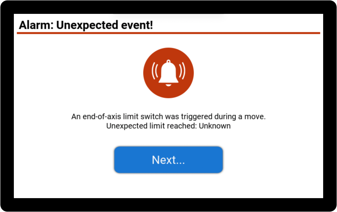
Over-sensitive limit switches
If you see an alarm with no obvious cause, it could indicate a limit switch failure.
An over-sensitive limit switch will be triggered when Z Head is not close to a magnetic field.
This will cause SmartBench to intermittently go into an alarm state when it is not close to either end of the X axis.
|
|
Details of which limit switch caused the alarm may show on the alarm screen, or if it “untriggers” itself quickly it may show up as “Unknown”.
|

If you have an oversensitive limit switch, you should record the alarm report (either by taking a photo, or plugging in a USB stick when the Console instructs you) and submit a support ticket with the information.
If there is no alarm screen
There may be an issue with the GRBL settings. Head to the CAD/CAM application on your console - Click on the settings cog on the right hand side to access the Gcode monitor (More information here on how to access the gcode monitor) - press the “Settings” button next to the GCode monitor, and in the output check that $21=1.
If it does not, enter “$21=1” into the textbox at the top of the GCode monitor, and press enter, close the warning and then press enter again. Then repeat the magnet test to see if the reed switch responds.
Replacing a failed X axis limit switch
Before replacing the limit switches, it's highly recommended to check which version of the Z Head you are using. Click here to learn about SmartBench Z Head versions.

Components needed
The X axis home and X axis max limit switches have slightly different slots, as shown in the image below:
L: X axis home - note the closed slots.
M: X axis max - note the open slots.

How to order a replacement limit switch
To get a replacement X axis limit switch, purchase a replacement from here or click here to request one by submitting a support ticket (If you are still within warranty)
Tools needed
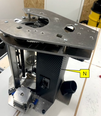
The limit switch connector is inside the Z Head casing, so you will need tools to remove this.
N: Casing
You will need the following allen (hex) keys:
O: 2mm allen key
P: 2.5mm allen key
Q: 3mm allen key

Remove the Z Head from the X Beam assembly
Click here to learn how to do this.

Opening the casing
|
|
The instructions in this section are for Z Head 2b onwards only - pictured above
|
|
|
Ensure you have plenty of space to lay out the components that will be removed from the Z Head before you start.
|
Start by removing the Z Head top plate.
R: Z Head top plate
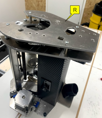
Use a 3mm allen key to remove all four bolts.

Once unscrewed, lift the top plate off the Z Head.

Pull off the four spacers highlighted in the image.

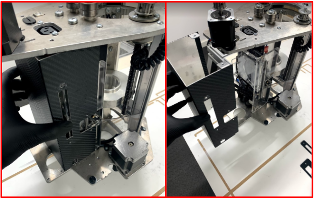
Next, we will remove the belt by first reducing the tension on the belt.
To reduce the tension, unscrew the four motor screws with the 2.5mm allen key.
S: Belt
T: Motor

And push the motor all the way towards the casing. This will take out the tension on the belt.
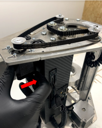
Now you can easily remove the belt as shown in the image.

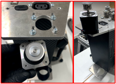
Unscrew the two screws which secure the top of the casing by using a 2mm allen key.

Fully unscrew the motor and remove it from the top of the casing and place the motor on top of the Z Head.
Remove the probe plate from the Z Head: unplug the probe plate connector, and then remove the probe plate from its housing.

Remove the dust shield on the probe plate housing by using a 2mm allen key.

Remove the dust shield on the probe plate connection socket by using a 2mm allen key.

On the left hand side of the Z Head, remove the signal cable shield with a 2mm allen key.

Remove the extraction elbow with a 2mm allen key.

Pull the casing away from the Z Head.
Secure all the removed components in a safe place, as you will need to re-fitting them later!

Re-fitting the Z Head 2b casing
To re-fitting Z Head 2b casing, click here to follow a step by step procedure.
Replacing the switches
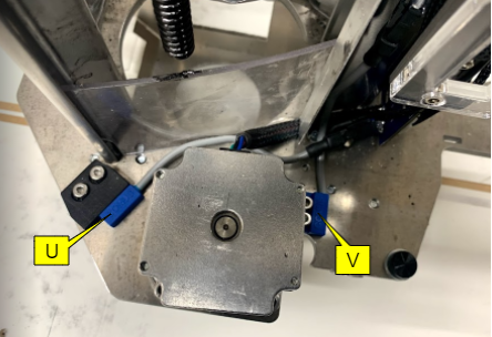
We will show you how to replace both X axis switches, although you may only need to replace one.
U: X axis home
V: X axis max
Replacing X axis home switch
The X axis home switch connects with the blue sleeve connector of the Z Head as shown below. Locate the connector and disconnect it by pressing down on the clip.
W: Blue sleeve connector from Z Head
X: X axis home switch

Use a 2mm allen key to separate the limit switch from its housing. Once unscrewed the limit switch tab can be pulled out to separate the switch.

To re-fitting the X axis home switch (whether new or old), click here to follow a detailed procedure.
Replacing X axis max switch
The X max limit switch connector runs vertically up the Z Head, as shown in the image.
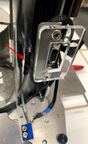
The X axis max switch connects with the black sleeve connector of the Z Head. Locate the connector and disconnect it by pressing down on the clip.
Y: Black sleeve connector from Z Head
Z: X axis max switch

Use a 2mm allen key to separate the limit switch from its housing.

To re-fitting the X axis max switch (whether new or old), click here to follow a detailed procedure.
| List | Next >