This article shows how to create cut toolpaths from the feature drawn in the previous step.
< Previous | List: First Project | List: CAD/CAM | Next >
Now that we have our tools created, it’s time to assign them to some toolpaths. Toolpaths will be generated based on the features we have already drawn.
For this tutorial we will assume we are using a 6mm flat end cutter and 6.35mm 90° v-groove engraving cutter with feeds and speeds which will work well with SmartBench.
|

|
For the purposes of this tutorial, we have provided nominal feeds and speeds based on the suggested tool. However, every tool is different, and you may find different speeds and feeds suit your cutter better. If you need to optimise, you can click here if you want to learn more about feeds and speeds in general.
|
|

|
When you apply a tool, Vectric will use the feed and speed settings saved in its tool database and apply them to the toolpath. After applying the tool, you can adjust the toolpath settings without changing the values saved in the database. You can click here to read about changing toolpath settings.
|
Engrave the text
Click on the text outline to select it and then click on the Toolpaths tab on the right hand side of the job screen. Select Quick Engraving Toolpath.
|
|
Hover the mouse over any button for a tip on what it does
|

Input the following parameters for Quick Engrave:
-
Select the engraving tool.
-
Depth of engraving: 2mm
-
Type of engraving: Outline
-
Post Processor: YetiTool SmartBench

Click Calculate. Note that a ‘Quick Engrave 1’ toolpath will appear in the list.

The preview of the toolpath will also appear in the 3D View tab at the top of the job screen.

Cutting holes
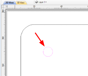
Switch back to 2D View tab.

Click on every circle while holding the Shift key on the keyboard to select all of them. Selected circles’ outlines will change to dotted magenta lines.
Click on Pocket Toolpath.

Use the following parameters for Pocket Toolpath:
-
Start Depth: 0
-
Cut Depth: 12.5mm (assuming we are using 12mm thick material and need to produce a thru hole, this means SmartBench will cut 0.5mm below the bottom surface of the stock)
-
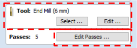
Select 6mm flat end cutter
-
Click on Edit Passes…

After clicking the 'edit passes' button we can now define the depths of each pass. There are several ways to do this, but for now we will use equal depth passes. In this example we will use 5 passes to get to the depth of each pass to be less than half of the cutter diameter.
Click on Set Passes
Click on OK to confirm

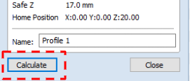
Click on Calculate.

When we click on Calculate, we will be warned that this will cut through the thickness of the material. This is correct as we want the holes to be through. Confirm by clicking on OK button.

Note that a ‘Pocket 1’ toolpath will appear in the list.

The preview of the toolpath will also appear in the 3D View tab at the top of the job screen.

Cutting a contour around the rectangle
Switch back to 2D View tab.
Select the contour of the sign. Click on Profile Toolpath.

Use the following parameters for Profile Toolpath:

Select 6mm flat end cutter
Click on Edit Passes…
After clicking the 'edit passes' button we can now define the depths of each pass. There are several ways to do this, but for now we will use equal depth passes. In this example we will use 5 passes to get to the depth of each pass less than half of the cutter diameter.
Click on Set Passes
Click on OK to confirm

Machine Vectors: Outside, Climb.

We need to keep our job in place once the contour is cut through. To achieve this, we will use tabs, which physically link the part to the remaining stock. Tick Add tabs to toolpath.
Specify the length of tabs to be 10mm and thickness 2mm.
Click on Edit Tabs...

We will use a constant number of 8 tabs and also select the option to avoid corners and curved regions.
Click on Add Tabs and then Close.

Click Calculate.
Vectric will warn the tool will cut through material. This is correct as we want the contour to be through. Confirm by clicking on OK button.

Contour will appear in the list.

The preview of the toolpath will also appear in the 3D View tab at the top of the job screen.

How to rename toolpaths
We strongly recommend renaming the toolpaths in a way you understand what cutter is used. Right click on a toolpath name and select Rename from the menu.

This will activate the name text. Type a new name and press Enter on the keyboard.

Repeat for all toolpaths to achieve a result like this:

What’s next
The job is now ready to be exported to a job file.
< Previous | List: First Project | List: CAD/CAM | Next >