A tutorial on how to draw and create toolpaths for 3D vectors in VCarve.
Drawing 3D Vectors in VCarve
First we will walk through the process of working with pre-existing 3D models that come with Vectric VCarve.
Vectric 3D models can be found in the ‘Clipart’ tab, and are divided into categories.

For this tutorial we will begin with a 3D dish, which can be found in the ‘Domes (Dishes)’ tab.

For this tutorial we will be using the 60° dome. Double-click the image to download it and place it in the centre of the sheet.
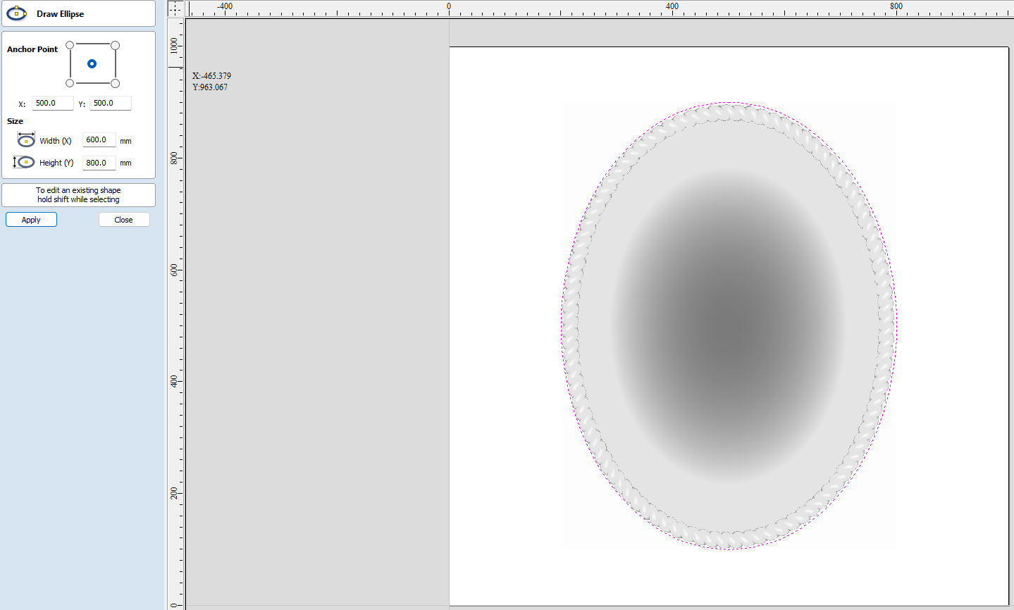
Next, we will transform the dish to an oval shape, as it will be forming the base of a portrait design. Select the dish and then select ‘Set Selected Object Size’.

Set the width (X) to 600mm and the height (Y) to 800mm, remembering to uncheck the ‘Link XY’ box.

Next we will add an oval border to this portrait, which can be found in the borders folder of the clipart section.

After double-clicking the icon to place it in the centre of the design, we will resize it to the same dimensions as the dish.
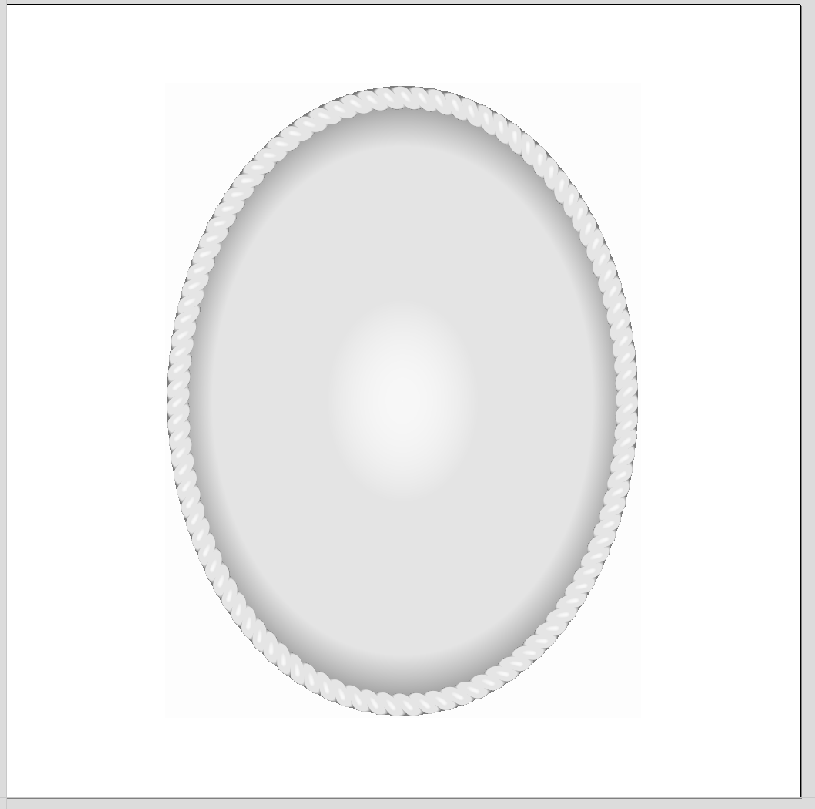
Finally, we need to add an ellipse vector around the components, to then use as a vector boundary when creating toolpaths later.
Modelling the 3D images.
The next step is to model the 3D bitmaps before we can designate toolpaths for them.
Open the modelling tab and switch to 3D view to better work with the model.

Before editing the 3D models, we need to add a Z-Zero plane that acts as the surface of our material for us to work with.
To do this click on the plane icon in the top right corner of the modelling tab.
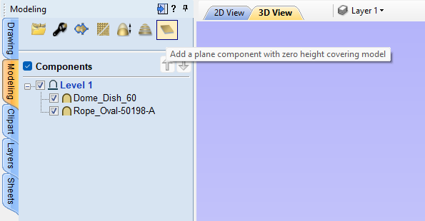
Next, double-click ‘Dome_Dish_60’ to edit its properties.

After setting the properties to those shown above, we need to edit the properties of the rope border component.
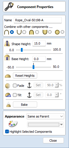
Note that it is being added to the previous component, and the height is set to 15mm so it will protrude from the highest point of the dish, but will still be flush with the surface of the material.
The model should then appear as so:

Creating toolpaths for 3D engraving.
It is best to split 3D toolpaths into two, a 3D roughing toolpath first, which we will use an end mill for, and then a 3D finishing pass, which will use a ball nose cutter. This is because by their nature 3D cutting takes much longer than 2.5D, so it is helpful to clear out space with a rough end mill cut, before the finishing pass can give rounded 3D detail.
Select both the dish and border component, open the toolpaths tab and select ‘3D Roughing Toolpath’.

First it will open up the material setup tab. Click here for more information on setting datums.

Clicking ‘OK’ will take you to the toolpath setup tab.

We are using a 6mm end mill, with the recommended feeds and speeds for softwood, please click here for more information on what feeds and speeds to use with SmartBench.
After clicking calculate, you can preview the roughing toolpath, which shows how the roughing toolpath is effective at clearing out the area, but does not give fine detail. 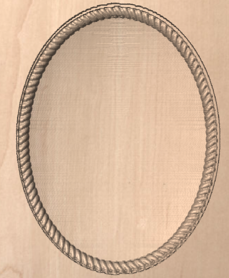
Next, click on the ‘3D finishing toolpath’ button next to the roughing toolpath.
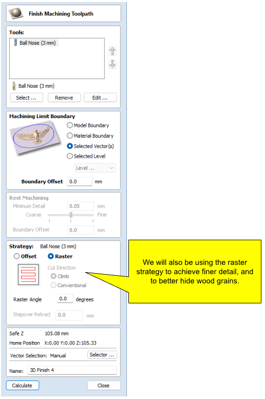
Then, press calculate and then preview the toolpath in the preview menu.

Finally, save the toolpath using the YetiTool SmartBench (*.gcode) post processor.
