< Previous | List | Next >
After reading this article, if you are looking to improve accuracy further this can be done through the best practice for accurate cutting checklist. Click here to read the checklist.
This is the section we will be looking at Vectric toolpaths

Ramps
This is a way of programming your job file to gradually, over the X and or Y axis, lower the tool bit into the cutting path, rather than plunging directly down into the material.
This is beneficial to remove any witness marks from tool deflection when plunging the tool bit directly downwards.
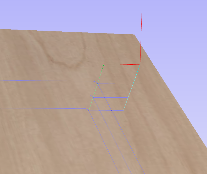
In the photos below. the red line is a move in air, the green line is a plunge in the Z-axis and the blue line is the drawn toolpath
A: Square profile with no ramps, so a direct plunge downwards

B: Square profile with a smooth ramp so it brings the Z-axis down while also travelling along

There are three types of ramps available to be aware of:
Smooth which has a distance that you can change of how far it travels along the toolpath while the Z-Axis is dropping
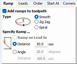
Zig Zag which in the same way goes out along your toolpath for a chosen distance (halfway down the Z-axis drop) and then returns back to the initial plunge X and Y axis position while dropping the rest of the way

Spiral which does a full loop along the toolpath while descending on the Z-Axis

Lead ins
Lead ins plunge down to the desired Z height and start cutting before entering the toolpath
This is useful especially for melamine faced material to prevent chips using a compression cutter as you do not want to use the upcut section to enter the top finished face first
Lead ins can also be used on any material using a compression cutter to achieve a nicer top face finish
Example compression cutter showing the upcut section:

C: Profile with no lead in
D: Profile with lead in
How to setup a lead in on Vectric:
Make sure add leads is ticked, pick between straight line or circular lead ins
If you would like a lead out of the toolpath make sure to tick the do lead out box
Lead length is chosen below - this defaults to 25.0mm

If you would like to select a specific start point, in the Start At tab click off “Optimise Start Points” and change to “Move Start Points to be closest to selected point on vector bounding box” and select one of the vector points


< Previous | List | Next >