This article is a list of common checks which you can run through if you encounter any X&Y accuracy problems while machining.
If you are looking for a Z-Axis specific article this is located here
To cut accurately, you need to make sure all of the tasks below have been checked.
Smartbench has a finished part accuracy tolerance of +/- 0.5mm
Check your Job File includes a "finishing pass" on critical faces
As the cutter moves through the material, cutting forces will cause the cutter to deflect. Depending on your job (step down, material hardness, cutter stiffness etc) this deflection can often be a common and significant source of error.
Where accuracy is important, it is standard procedure (for any CNC operation) to include a finishing pass. Adding a finishing pass runs the cutter back over any critical surfaces to complete the removal of any material that may have been missed due to deflection. Finishing passes are easy to add during the job file creation stage. To learn how to add finishing passes in Vectric, click here.
Use as short a cutter as possible
Cutting with an excessively long cutter will unnecessarily magnify any tool deflection while running the job, causing inaccuracy. Make sure your cutter length is as short as possible.

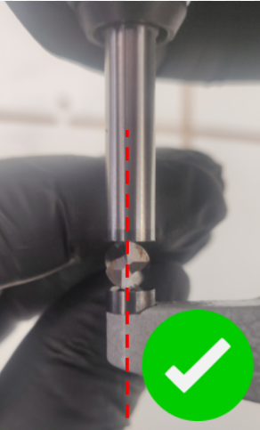
Ensure your cutter is correctly loaded
Make sure that your cutter’s shank is not touching the back of the spindle taper, which can cause the cutter to rotate eccentrically, causing inaccuracy in the cut. Click here to understand the correct procedures of loading a tool into the collet.

Check your cutter condition
Used cutters will deflect much more than new cutters and cause inaccuracy. Click here to learn how to check your cutter condition. Badly worn cutters can also introduce stalling.
Use a higher quality cutter
By using quality toolbits, these will last longer and will not shrink in size as quickly due to the longer time it takes for them to wear down. They will also remain sharper for longer.
Here is an example of when you should pick a higher quality tool bit from our aluminium cutting guides

Check your cutter actual diameter
The diameter of your cutter plays an important role in cutting the job file. For instance, if you are after a precise cut with a cutter diameter of 8mm but in reality due to the manufacturing processes, the actual dimension of a cutter can be slightly different from the nominal size. We recommend measuring your cutter from the tip and use this measured value when creating your job files.
It is also common to accidentally design a job file with a metric diameter, but use a "close" imperial diameter, and forget the difference. E.g. if a job file is for a ø 6 mm cutter, but a 1/4" (ø 6.35 mm) cutter is used, the finished part will immediately be 0.35 mm smaller than expected.
Click here to learn more about measuring your cutter.
Use appropriate feeds & speeds
Cutting your job with inappropriate feeds and speeds can also deflect the cutter or stall the axes, causing inaccuracy. Click here to understand appropriate feeds and speeds for SmartBench
Feeds and speeds for small circles
When cutting out small circles we do also recommend reducing the recommended feed rate. This will reduce the deflection effect on the tool bit of the constantly changing direction.
Ensure good workholding
If your stock material is not properly clamped, it may shift position when machining, affecting the geometry of your finished part.
Where possible screwing in stock material would result in the least material movement
Click here to learn more about workholding.

Use manual squaring instead
By using a manual square rather than auto square on startup exerts less stress on the motors and results in better repeatability than auto-squaring.
Check your extraction
If dust is not evacuated properly it can get compacted and start deflecting the cutter, causing inaccuracy
For SmartBench we recommend a MINIMUM flow rate of 70 l/s (litres per second) with a maximum hose length of 1.5 metres. Having a shorter hose length reduces the loss of extraction flow rate from the extractor through the hose.
By having a higher extraction flow rate this will prevent dust and debris blocking the channel and causing tool deflection, we recommend a minimum of 70l/s with a maximum hose length of 1.5 metres for standard application however if you are looking for increased accuracy we recommend increasing this minimum specification and where possible use a shorter hose or connecting your extraction hose directly to the Z-Head
Having a shorter extraction hose also prevents issues with static buildup and stalling

Click here to understand your SmartBench extraction requirements and how to visibly inspect the performance of your extraction.
Click here to learn more about what extractor types and fittings work best with SmartBench.
Click here to know how to choose a correct toolpath strategy to prevent extraction blockages
When available Upcut toolbits will aid in the extraction of swarf more than downcut toolbits
Check your spoilboard and Lead screws for Z axis accuracy
A spoilboard thicker than 12mm will prevent the beam's ability to iron out any material depth variances and may result in Z axis inaccuracies
Cleaning and greasing the Lead screw(s) every 50 hours or when necessary will prevent stalling on the Z-axis and reduce motor load
Keep your wheel channels and racks clean
Debris in the axes can deflect the assemblies, which can affect accuracy. Click here to learn how to correctly clean your machine axes before a job.
Calibrate your machine
The distance travelled by the machine axis may vary after calibration due to the following reason:
Calibration is an essential part of correcting for this. Click here to learn how to calibrate your machine. A DIN 866 Form A metal rule will have the best accuracy (which has a tolerance of ±0.06mm for 2 metres) or if using a tape measure ensure you are using a class 1 tape measure (which has a tolerance of ±0.3mm for 2 metres)
Check the probe plate thickness, to do this use a micrometre and follow the guide here
Support the upper beam rollers
Ensure the upper beam rollers are always being supported at the same height and that they are not travelling over a rough surface. Click here to learn more about this

Spindle best practice
Ensure your spindle is clamped correctly along with the best cooling process, Click here to learn more. This can reduce spindle free running load by up to 50%
Also ensure your brush wires are inserted the correct way round to reduce the chance of spindle power issues during your job
Maintenance
Check if your machine is scheduled for any routine maintenance pay close attention to the Z-Head and Lower beam wheel setting and where greater accuracy is required reduce the 120 hour timescale where necessary.
Ramps and Lead ins
Ramps and lead ins prevent any accuracy issues of plunging the tool bit directly into the material we have a guide for how to set this up in Vectric here
Lead ins are particularly useful for compression cutters to prevent tear out on the top and bottom face of your finished parts
Checking your CAD/CAM setup
Check through our material profiles and datasheets for all our up to date material strategies
Ensure you are using G2 and G3 commands for arcs and circles rather than G1 commands which are designed for straight lines. If you are using Vectric this is how to set this up, you will want to select "Circular Arcs". If you are using Fusion this is how to set this up via the smoothing option on your toolpaths.
After you have exported, check your Gcode or NC file on https://ncviewer.com/. You want to ensure that circles and arcs are round and not shaped like the below which would indicate you are either using G1 commands or the CAD program you are using has an inaccurate exporter

Preventing tool bit deflection
By using shallower passes this will reduce any cutter deflection
By using larger diameter cutters they will be less affected by tool deflection than a smaller diameter cutter
Choose between climb and conventional, more information on our essential cutting strategy parameters article
If possible do not swap between climb and conventional on the same cut choose a consistent direction for the whole job otherwise you could be introducing inaccuracies from the switching strategies
Tolerances
If you are designing for parts that fit together it is important to understand tolerances and their importance to finished part accuracy. We have a guide which details the full process
located hereMeasuring your finished parts
Ensure you use an accurate set of callipers if you are measuring your finished parts
Thermal deformation
Changes in temperature during a cut can expand or contract your material and Smartbench itself. Ensure your material is cut outside of any large temperature changes and that there are no heaters turned on halfway through a cut or an aircon unit is switched on.
Also be aware your extraction exhaust can introduce a lot of heat to your workshop
We recommend recalibrating your Smartbench if it has been subjected to a large or quick change in temperature
Ensure all movement of Smartbench is clear of obstruction
Ensure that Smartbench is free to move around without any addtional causes of stalling or drag. Examples of this is having tangled power cables dragging excess objects, extension leads or extraction hoses around underneath your Smartbench.