This article will show you how to install your BigFoot.
< Previous | List | Next >
Before you start
Before beginning this process, we advise you to place your BigFoot upside down on a flat surface. (So the hose is pointing downwards)
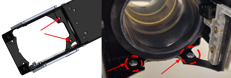
Take two of the supplied M4x8mm dome head screws and thread them through the holes shown using your 2.5mm hex driver. This will make installing the Z Head later much easier.
Step 1 - Fit dust shoe loom
Plug the original dust shoe loom into the socket of the splitter loom.
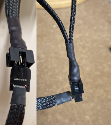
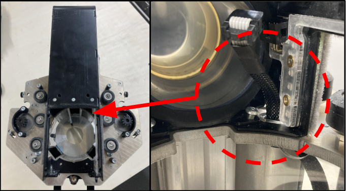
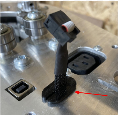
Feed one end of the supplied splitter loom through the strain relief hole in the Z Head base plate as shown. Either end of the loom can be used as it is designed to be reversible, ensure the end is orientated as per the below photo.
|

|
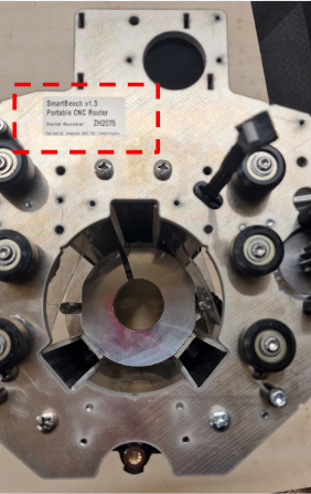
Note down your Z-Head serial number at this stage, since this will be covered by the BigFoot once installed. This begins with ZH and ends in four numbers
|
Step 2 - Attaching BigFoot
Now lower the dust shoe into place and feed the loom through the hole into the dust shoe.
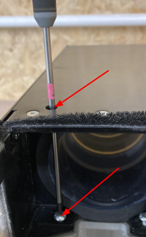
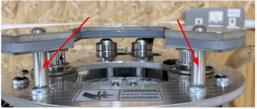
Partially thread the two screws you positioned before, into the receiving holes in the Z Head base plate. It is recommended to use a long 2.5mm hex driver and access the bolt heads through the shown holes.
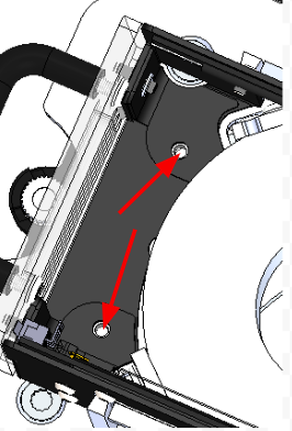
Now install the other two M4 x 8 dome head screws in the holes shown below and tighten.
You can now fully tighten the first two M4 x 8mm screws.
Step 3 - Install the splitter loom
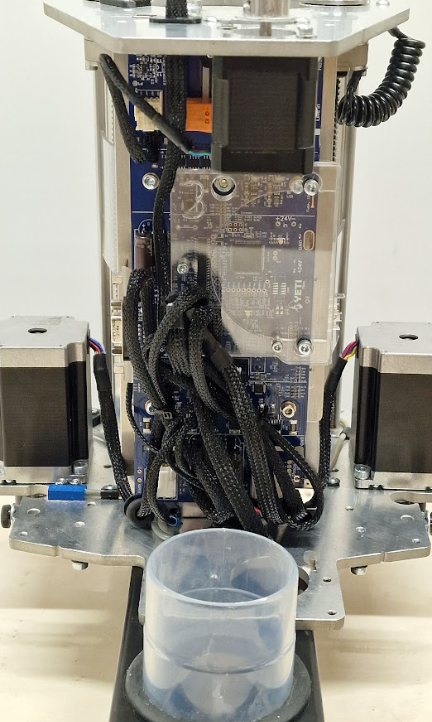
Plug the Halo splitter loom into the PCB in your dust shoe. You may find it helpful to use a pair of long, needle nose pliers to do this.
You can now flip your Z Head back over into normal orientation.
Fit the strain relief clip onto the splitter loom from the top of the Z Head base plate.
While gently pulling on the loom to remove any slack in the dust shoe. Slide the strain relief down and push it into the hole in the Z Head base plate. Do not pull too hard, as the connector and loom are delicate
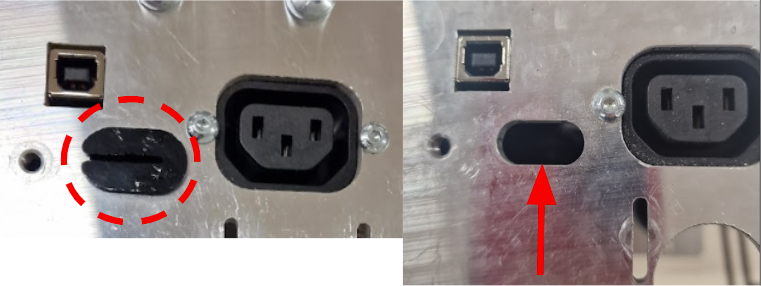
Step 4 - Removing the strain relief
Remove the strain relief clip from the Z Head motor plate by pushing from the underside.
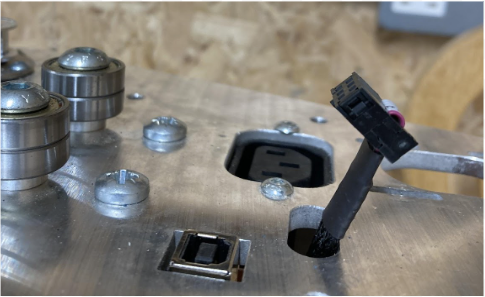
Step 5 - Routing the splitter loom
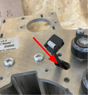
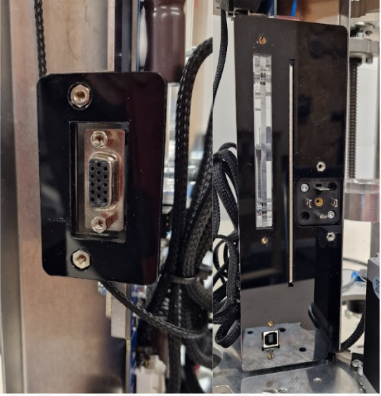
Feed one end of the splitter loom through the hole in the Z Head motor plate, ensuring that the connector points towards the front of the Z head as shown.
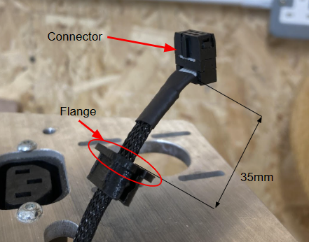
Step 6 - Installing the strain relief
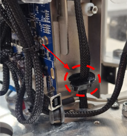
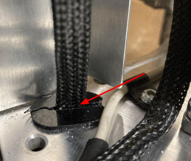
Slide the loom into the slot of the strain relief clip, with the flange facing the connector, and pull the loom through until there is ~35mm exposed.
Push the strain relief clip back into the Z Head motor plate so the flange is snug against the top of the plate.
Step 7 - Routing the loom
Route the loom tidily with the rest of the looms so the rear cover can fit over them.
Reassemble the Z Head
Now you can reassemble your Z Head.
Step 8 - Remove the Z axis motor
First, in order to refit your rear electronics cover you will need to once again put your Z axis motor on top of the Z Head top plate.
To do this, remove the two bolts temporarily fitted to hold the Z motor in place using your 2.5mm hex driver, taking care to support the Z motor as you do so.
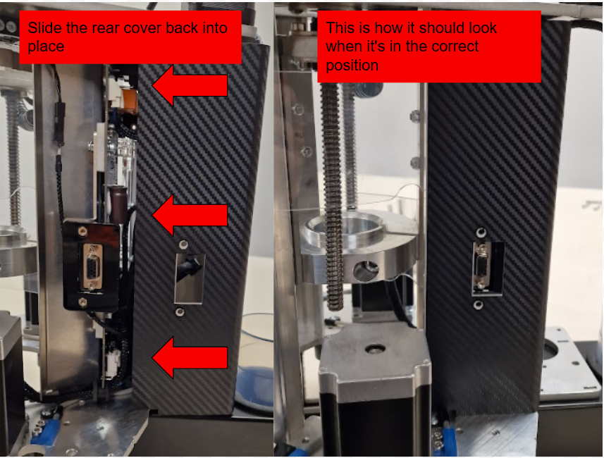
Step 9 - Refitting the rear cover
Re-fit the acrylic spacers onto the Z Head
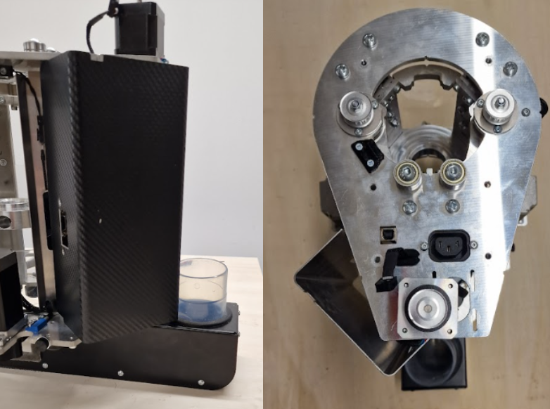
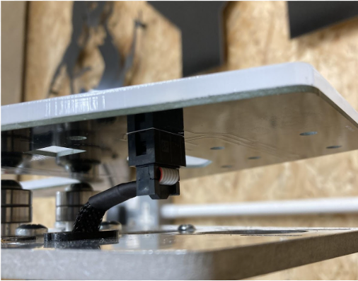
With the spacers in place, you can now reinstall the rear electronics cover. You will need to fit the cover on from an angle in order to avoid the BigFoot extraction port as shown below.
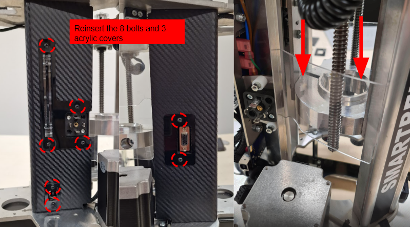
Step 10 - Reinstalling cover plates
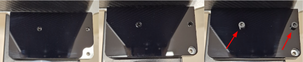
Using a 2mm hex driver and 8x M3x6 bolts, reinstall the acrylic covers. You can now slide your acrylic windows back down into place.
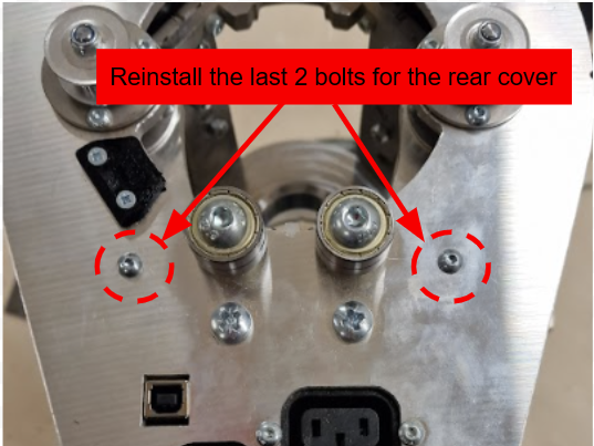
Step 11 - Securing the rear cover
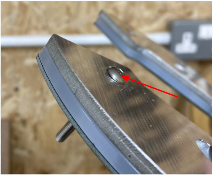
Secure the cover by refitting the 2x M4x10 bolts to the top of the Z Head, shown below.
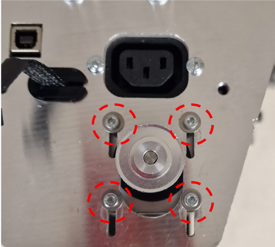
Step 12 - Refitting the Z motor and belt
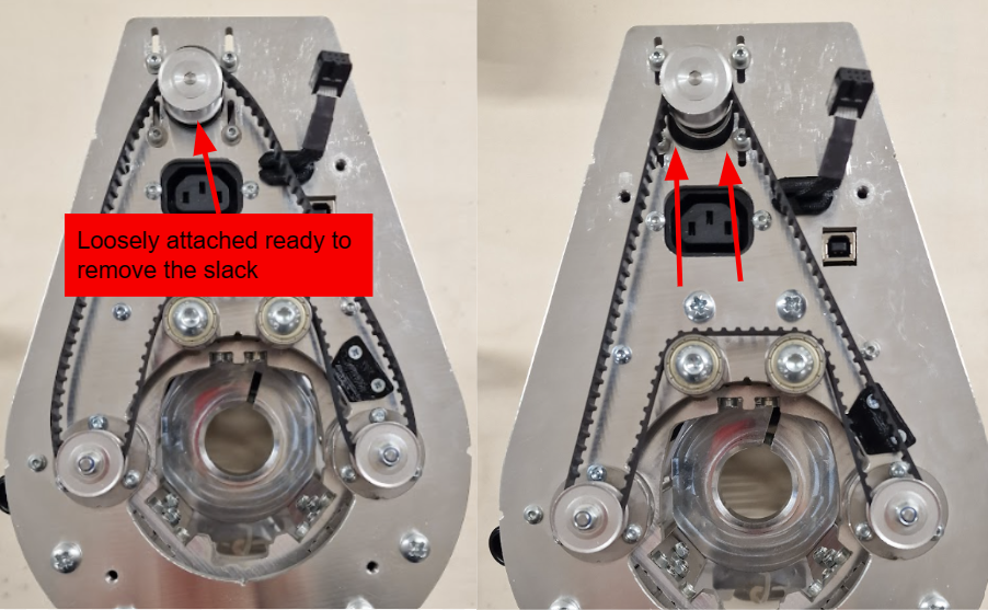
Finally, refit your Z motor.
Using the 2.5mm hex driver, loosely thread the 4 bolts with washers into the Z axis motor, taking care to support the Z motor as you do so.
Once loosely secured, you can refit your motor belt as shown below.
Gently pull your Z motor so that the belt is tight. You can then tighten the motor bolts.
Step 13 - Installing the rear cover plates
Using a 3mm hex driver, fit the lower and upper parts of the acrylic rear cover plate onto your Z Head where your original dust shoe elbow was, in the orientation shown below, and fix it in place with the two M4x10 bolts.
Step 14 - Installing the halo PCB
Plug the loom into the halo PCB as shown below.
Place the top cover plate on top of the halo PCB diffuser, and insert the two M5 x 40 Dome Socket bolts at the front using a 3mm hex driver. Take your spacers and loosely thread these bolts onto the Z head top plate.
|
|
Do not tighten the bolts until all four spacers are in the correct position
|
< Previous | List | Next >