The article guides you through removing your standard dust shoe from a V1.2b/ V1.3 Z Head.
< Previous | List | Next >
Checking your version
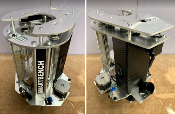
The BigFoot upgrade kit is only compatible with Z Head V1.2b onwards which looks like the one below.
If you are unsure on which Z Head version you have, then please submit a support ticket here.
Before you start
You will need:
-
2mm hex driver
-
2.5mm hex driver
-
3mm hex driver
-
Tweezers
-
Long nose pliers
-
Flat head screwdriver
Preparation
|

|
Ensure that you have removed the spindle motor and that the spindle cage is raised to the top of the Z Head. Then remove the Z Head from your Smartbench before proceeding with this process.
|
Z Head disassembly
Step 1 - Remove the top plate
Using a 3mm hex driver, remove and discard the four top plate bolts. Remove the top cover plate and the four spacers. You will need these later.

Step 2 - Remove the extraction elbow
Remove the extraction elbow and O-ring using a 3mm hex driver.

Step 3 - Remove probe plate
Unplug and remove the probe plate.

Step 4 - Remove the Z axis motor
Remove the 4 bolts holding the Z axis motor using a 2.5mm hex driver and then remove the belt. Once this has been removed you may rest the motor on top of the Z Head ready to remove the rear cover.

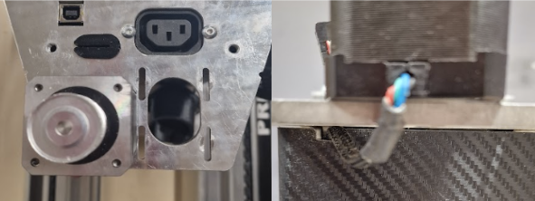
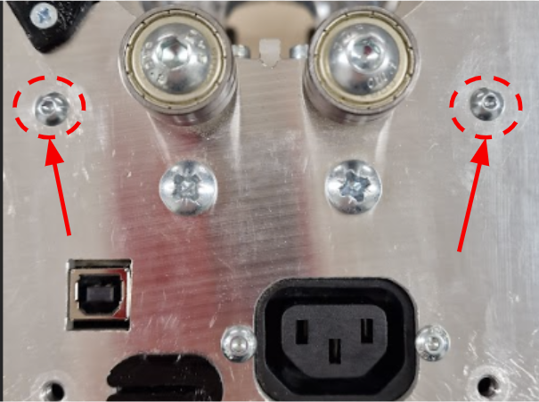
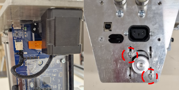
Step 5 - Remove the rear cover
In order to remove the rear cover, you first need to remove the two bolts shown below using your 2.5mm hex driver.
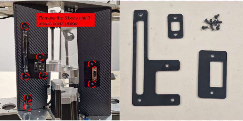
You can now remove the 8 bolts on either side of the Z Head shown below with a 2mm hex driver, including the acrylic spacers.
You are ready to remove the rear electronics cover. Ensure that the Z motor does not fall when doing this step.
Flex the cover outwards (as below) as you pull the cover slowly back towards you. Once removed you will see two acrylic spacers (once each side) which you can now also remove.
Step 6 - Secure the Z motor
With the electronics exposed, you can now temporarily secure the Z axis motor to the top plate loosely using 2 bolts to ensure it is not knocked during the rest of this procedure.
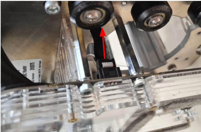
Step 7 - Unplug the dust shoe loom
Next, unplug the dust shoe loom from the existing dust shoe. This is located on the left hand side of the extraction port, on the underside of the Z Head.
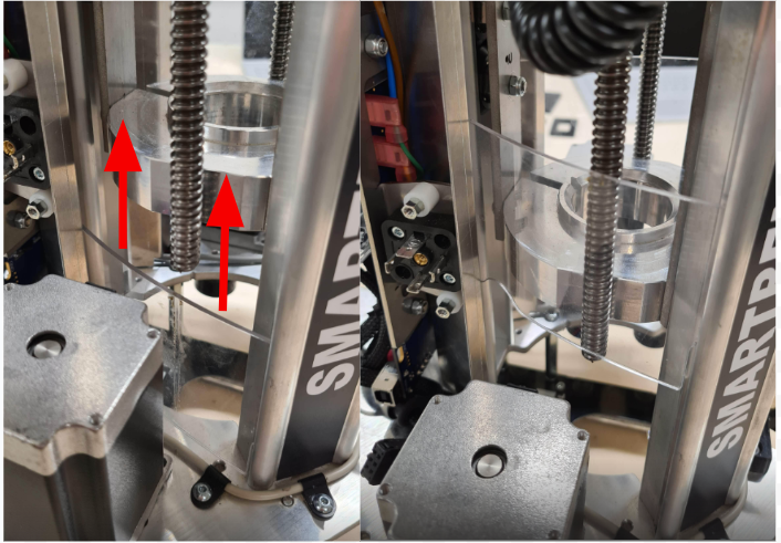
To gain access to the bolts holding the dust shoe in place, you will first need to slide up the side windows on the Z Head.
Slide up the Z Head side windows about 5 cm. You will need to bend the windows slightly in the middle as you pull them up to clear the lead screws.
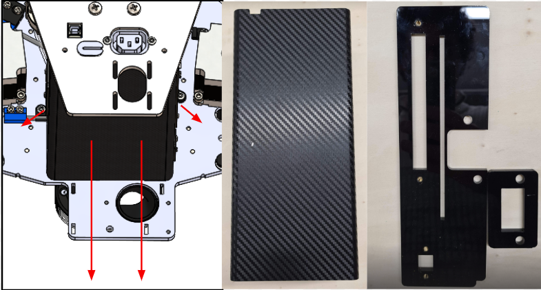
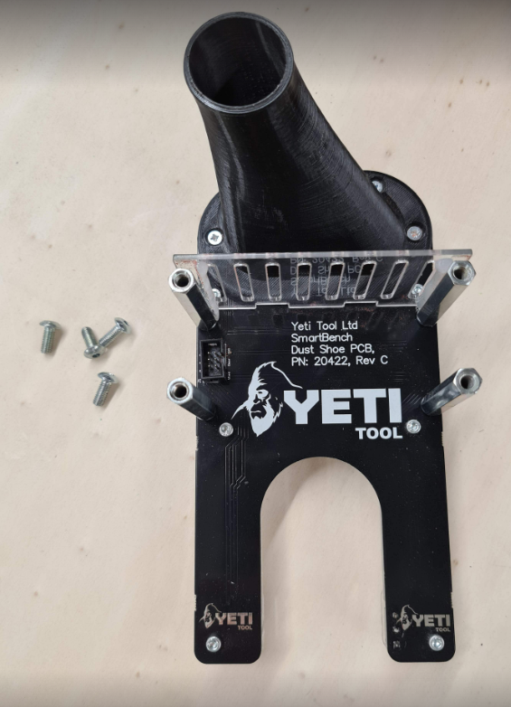
Step 8 - Remove the standard dust shoe
Now you are ready to remove the standard dust shoe.
First, position the Z Head so that it’s resting on its side; this is important to prevent the Z Head from falling over when the dust shoe is unbolted. Then remove the dust shoe by removing the four bolts shown below, using a 3mm hex driver.

Place your Z Head upside down.
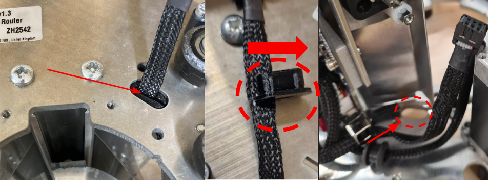
Remove the dust shoe loom from strain relief in the Z head bottom plate by pushing the strain relief through the Z Head plate and sliding the strain relief clip off of the loom. Push the loom through to the Z Head electronics
You can now proceed to the next step.
< Previous | List | Next >